![David Molnar [Update:, PhD]](https://www.srcf.ucam.org/~dm516/wp-content/themes/twentyeleven/images/headers/chessboard.jpg)
I believe many lab robots are scrapped purely because the control computer and the control software become obsolete. With the ability to write new software such robots can become useful again, and not only in DIY-bio settings. There is however very little documentation as far as I can see. I had opportunity to experiment for a weekend with an Ettan Spot Picker lab robot, and found that reverse engineering its communication protocol was not very hard. Unfortunately most of my documentation in text files and programs were eventually lost together with the old command computer of the robot, as I forgot to move them off. I hope what is left can be still of some help in starting, if someone is in a similar situation.
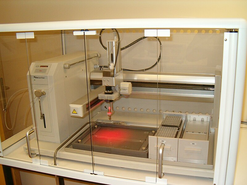
An Ettan Spot Picker (Wikimedia Commons).
The robot normally punches out little pieces of protein electrophoresis gels and collects them in tubes, so that the fractions can be further analysed, e.g. with mass spectrometry. This is also the only thing its control software on the PC permits to do. The robot itself is an arm with a tool holder that can move in X-Y-Z direction, switchable power sources for tools on the arm, and a controllable syringe pump. It likely could be modified for other tasks.
I found the robot to communicate through a 9-pin D-sub connector with a controller card in a Windows NT computer (it really was old). Communication was via GSIOC ( Gilson Serial Input Output Channel), a slight modification to the RS232 serial protocol. Although the pin layout was the same as RS232, I could not get it to work with a normal PC serial port. This was probably because electrically GSIOC seems to use RS-422 signal levels, which are higher than RS232 levels. GSIOC (together with RS232) has been widely used for lab automation at some point, and in my limited experience I have seen it not only on other robots but also on HPLCs, sample collectors and pumps. As their mode of communication becomes obsolete, this group of machines might be now a source of cheap equipment.
Reverse engineering of the protocol: I found no way to intercept the commands from the manufacturer’s software with the limited means of the control computer. It was possible however to send and receive text through a COM port with a terminal emulation at 19200 baud. The battle plan was therefore to essentially fuzz the machine with commands via the COM port until it started doing things, which happened quite early: commands turned out to be short combinations of letters and zero-padded four-digit numbers. The command bH for example homes and calibrates the arm in the X-Y-Z directions.The command bX1000/1000 moves the arm in the X-Y plane to the position X:1000, Y:1000. Along the Z axis bZ1300 moves the arm to its uppermost position, and coordinates decrease downwards. A little bit of caution is needed here as it is very much possible to try to move the arm further up or down than the attached instrument holder permits. There are further commands for controlling a switchable power source for tools on the arm, to change the display, and to read out sensors and state variables of the robot. Unfortunately these I lost with my documentation.
For a bit of entertainment and to test my newfound abilities I put a mechanical pencil with a spring to push it down into the tool holder of the arm, and used the robot as a plotter. I could not find software that would run on the control computer, but fortunately it had Word, and with that Visual Basic. So this was an opportunity to make the acquaintance of this language and it could indeed send commands through the COM port. I quickly wrote a little library of common functions, and algorithmic drawing is so much more fun if done with a pencil.
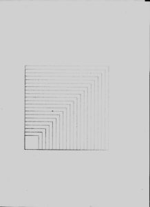
One of the first calibration drawings.
To make more complex drawings I had to use a contemporary laptop as the controller. The NT machine could deal with ethernet and IP, and VB could even implement the equivalent of netcat. So eventually I relegated the control computer to forwarding commands from ethernet to the COM port, and produced the control sequences on the laptop. Fortunately Inkscape can export drawings as HP-GL, which is a language for controlling plotters, and contains exactly the kind of commands I needed. A little Python script converted the limited HP-GL vocabulary that Inkscape uses to Spot Picker commands and sent them on to the VB bridge on the Windows NT control computer.
In summary, I believe once there is a bridge to GSIOC or RS232, getting a lab robot to work can be quite quick, and it certainly is a fun thing to do on a weekend. Many thanks to Kathryn Lilley and the Proteomics Group for kindly letting me have their machine for some experiments instead of just getting rid of it.